The following brief paper is reproduced from Power Quality Assurance magazine, March/April 1998, pp. 72-73.
Transferred Earth Potential
Tom Shaughnessy, PowerCET Corporation, Santa Clara, California
____________________________________________________________________________
The IEEE Green book Std, 142-1991, IEEE Recommended Practice for Grounding of Industrial and Commercial Power Systems, contains specific information in sections 1.6.4, 1.6.7 and 4.2.6 pertinent to transferred earth potential (TEP). Section 1.6.7 is most specific:
The term transferred earth potential refers to the voltage-to-earth of grounding systems that will appear on conductors as a result of the source system grounding electrode being above normal earth potential. The larger voltages are usually developed by ground fault currents returning to their source through earth. A common example is a ground fault of a conductor, which is supplying a substation transformer primary, to the station ground grid that is used for grounding of the transformer secondary neutral. If this grounding grid is not connected to the high-voltage source system ground, there can be a significant voltage rise above earth as the fault current flows into the earth. Low voltage conductors leaving the area where the ground or the grounding electrode voltage has been affected will have the voltage added to their normal line-to-ground voltage. The total voltage may exceed the insulating rating of the conductors or the equipment to which they are connected.
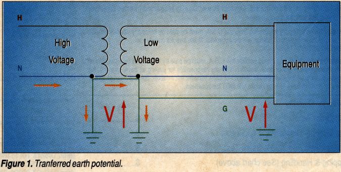
While the focus of the Green Book vis-a'-vis TEP revolves primarily around substation grounding, the principles apply to facility grounding as well. In a poorly grounded facility, fault and lightning stroke conditions may cause substantial current flow to ground. The current flow interacting with the impedance of the facility grounding will develop voltage. This voltage, in turn, will cause ground voltage rise within the facility. Figure 1 illustrates this condition. The rise in potential can be measured at equipment. An earthed reference such as a water pipe or driven ground provides a good measurement point.
Transferred earth potential occurs most frequently if the grounding of a facility is less than desirable (or adequate). For instance, seasonal variations in earth resistivity due to moisture content (dry) or temperature (frozen) can lead to thousands of ohms per centimeter earth resistivity. In this case, even small amounts of current flowing to earth can cause elevated potentials within a facility. If facility grounding is poor and the grounding of utility transformers (pad and pole mounted) is also weak, then the effects of TEP will be worse. Wye-to-wye supplied facilities may be more prone to develop TEP problems.
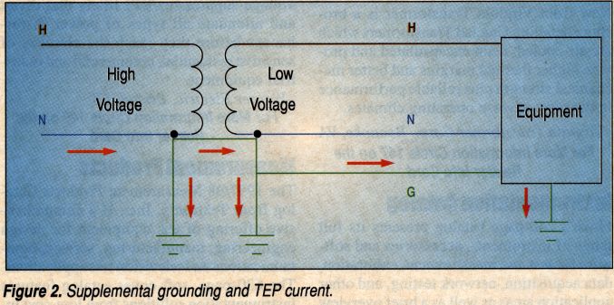
As stated in the Green Book, the voltage rise can adversely affect wiring and equipment within a facility. Two conditions can aggravate conditions at equipment affected by TEP: supplemental grounding and data connectivity. Supplemental grounding (e.g., attaching separate driven ground rods to the chassis of equipment) provides a path through the equipment that is parallel to the grounding at the service entrance. Therefore, surge current flowing to ground at the service entrance will also find a path through the equipment. Figure 2 shows this condition. If the voltage rise at the service entrance is very large, then the resulting TEP potential will drive large amounts of current through the equipment grounding to the supplemental grounding of the equipment. It is for this reason that electrical inspectors often require that supplemental grounding use must meet the effective grounding provision of the NEC per article 250-51.
TEP can adversely affect data connectivity. When data connectivity provides a metallic path between one devise affected by TEP and another device at earth potential, then upset or hardware damage can occur. In the case of balanced, differential data networks (e.g., RS-422) earth referenced voltage potentials may exceed the withstand capabilities of the network interface cards. At the very least, data transmission problems may occur. At the worst, potentials will exceed the dielectric withstand capabilities of the network cards and hardware damage will occur. With unbalanced, single-ended networks (e.g., RE-232 or RS-423), the network connectivity to ground at each end of the network affords TEP currents a path to follow. If sufficient current flows through the path, then data transmission problems will occur, and if current flow becomes excessive, then data interface cards will fail.
TEP problems can be avoided by ensuring adequate grounding at the service entrance and at utility service transformers. Most IEEE standards recommend earth resistivity of less than 5 ohms for a facility. TEP problems can be aggravated by adding ground rods within a facility and by extending a metallic data network between equipment served by separate earthing systems.
Click here to download a PDF of this page.
